

Testing Summary
The components of the RC Baja vehicle were tested and evaluated by Paul Lervick. Specifically suspension coil, the chassis, and the control arms. Each component had a test. The suspension coil had a drop test. The chassis had a center loading test. The control arms had force testing. These tests were done to ensure that each component meets its requirements.
There was challenges during each test that were experienced. Most notably, a problem during the chassis deflection test. It was challenging to actually measure the deflection accurately as it was a very minor amount of defletion in a challenging location to measure. Forturnatly, a fellow classmate, Ryan Lafrmanbois, suggested the use of feeler gauges as he ran into a similar problem. This measuring tool solved the problem by enabling accurate measurement in awkward locations.

Figure 1: Suspension Test Measuring Device In Resting State

Figure 2: Suspension Compressed From 3 Foot Drop
Drop Test
First, the drop test was done to see if the suspension met the requirement of not compressing more than 50% of its free length when dropped from 3 feet. This was done by recording the RC car on the floor when it met the ground in slow motion. There was a measuring device attached to the suspension coil that the slow-motion video would be able to track and gather data on as seen in Figures 1 and 2. The suspension had a maximum compression of 28% and the RC car survived all the drop tests and was fully functioning afterward. The slow-motion videos to capture this data can be seen in Figure 3.


Figure 3: Slowmotion footage of the 3 trials
Chassis Deflection Test

Figure 4: Deflection test setup

Figure 5: Highest deflection load
To meet the requirement for this test, the chassis mustn’t deflect more than 0.05 inches when a 10-pound load was applied to the center. It was found that it took 42.5 pounds of force to reach a deflection of 0.04 inches. So, yes it met the requirement, but why did it exceed it by so much? This is because the 1/8th inch aluminum chassis that was chosen was readily available and easy to manufacture. The Setup of the test can be seen in Figure 4 and the chassis with the max load can be seen in Figure 5. Also, all the data gathered for the test can be seen in Table 1.

Table 1: Deflection Data
Control Arm Deflection Test
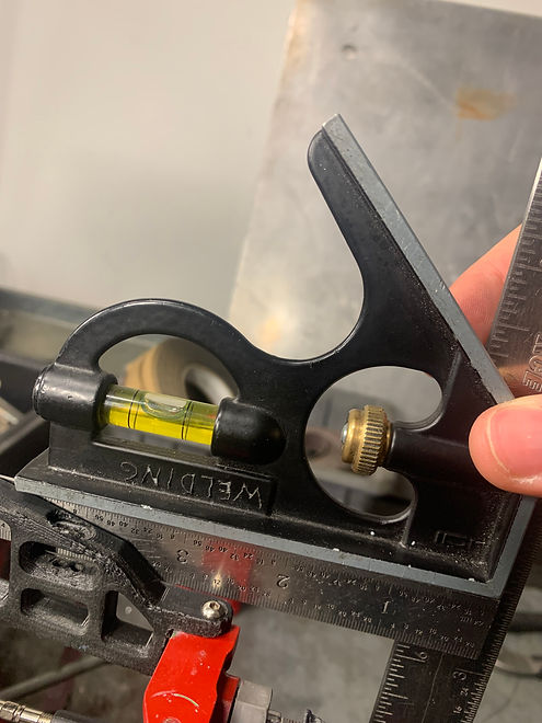
Figure 6: Square edge for taking measurements off of.

Figure 7: Mechanism for applying load to control arm.
To meet the requirement for this test, the control arms couldn't deflect more 0.03 inches when a 10 lb load was applied at the end of the arm. It was found that when a 10 lb load was applied the deflection of the control arm was .026 inches as seen below in Figures 8 and 9. So, the control arm did meet the requirement set for it. Figures 6 and 7 display the set up for the test as see above.

Figure 8: Maximum deflection of control arm.

Figure 9: Control arm with applied load.