

Construction Summary
The LJM RC car is comprised of many components. Some of these components were purchased such as the suspension shocks and the wheels. But, for the components that were designed, many manufacturing methods and materials had to be considered for each component.
Drawing Tree:

Manufacturing Process Below:
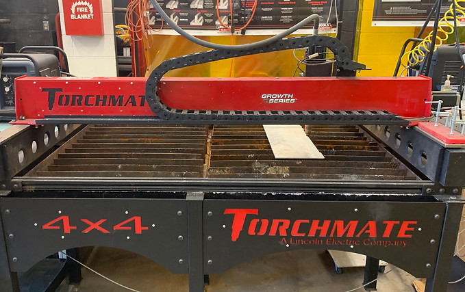
Figure 1: Torchmate CNC Plasma Cutter.

Figure 2: Plasma Cutter in Action.
The manufacturing method for the Chassis plate was to first have it be CNC plasma cut on the Torchmate Machine at Central Washington University with the help of Chris Berkshire. This machine and the cutting process can be seen above in Figure 1 and Figure 2

Figure 3: Suspension Components fresh out of the 3D printer.

Figure 4: Suspension components cleaned and on chassis.
For all of the designed suspension components, the manufacturing process that was chosen was to 3D print them due to its ease, low cost, and relatively high material strength. The control arms, and suspension towers were printed at the Multimodal Center at CWU with the help of Maggie Romero. Images of the components printed oriented on the chassis can be seen in Figure 3 and Figure 4 respectively.

Figure 5: Drilling chassis plate.
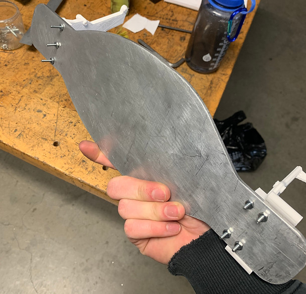
Figure 6: Chassis plate with suspension towers fastened.
The final manufacturing process for the chassis was to have all the holes drilled to allow for attachment of all the components. This was done using the drill press in the machine shop at Central Washington University. Images and videos of the chassis can be seen in Figure 5 and Figure 6.

Figure 7: Front suspension assembly.
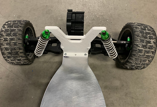
Figure 8: Rear suspension assembly.


After all the suspension components were manufactured they could be attached to the chassis using fasteners. To mount purchased components such as the wheel hubs and shocks to the 3D printed components, it required to the 3D printed components to be drilled and tapped allowing strong points of connection to the components. Images of the front and rear suspension assemblies can be seen in Figure 7 and Figure 8.
Finally the entire suspension assembly was functional. The car could now roll and be dropped allowing the springs to absorb the impact of fall. To have proper camber on the wheels the upper control arms had to be shortened in length which optimized function of the suspension. Images and videos of the suspension and chassis assembly can be seen in Figure 9 and Figure 10.
Figure 9: Video of suspension assembled.
Figure 10: Full suspension assembled.


Figure 11: Old Suspension Coil.
Figure 12: New Suspension Coil, Rear.
Figure 13: New Suspension Coil, Front.
It was found that the suspension was actually too soft. To correct that there were stiffer springs and spacers put on the suspension struts to decrease any sagging that the car would experience. Images of the suspension springs can be seen in Figures 11, 12, and 13.
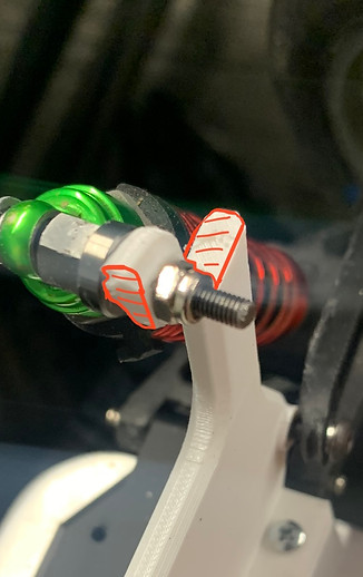


Figure 14: Front Suspension Tower Fail.
Figure 16: Control Arm Connector Fail
Figure 15: Rear Suspension Tower Fail.
While assembling and giving the vehicle its initial loadings, there were a few 3D printed components that failed or were delaminated. This led to minor redesigns and reprints of components in different orientations to enhance their strength in the desired plane. Images of the suspension springs can be seen in Figures 14, 15, and 16.
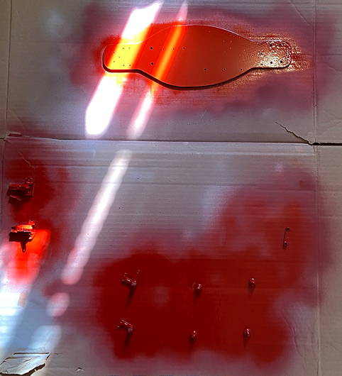
Figure 17: Painting Components

Figure 18: Painting Wheels
Style is important to the LJM RC Baja team. So, we 3D printed all our components in black and painted the other components in crimson red for a CWU theme as seen in Figures 17, and 18.

Figure 19: Assembling full RC car.

Figure 20: Final fully constructed RC car.
Finally, the RC car was to be completely assembled. while there may be a few minor adjustments made, the final functioning RC car can be seen in figure 20. The assembling of the car can be seen in figure 19. Style is important to the LJM RC Baja team.

Figure 21: Final fully constructed RC car.
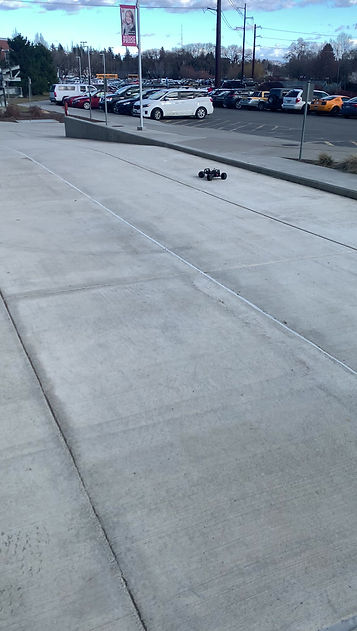
Figure 22: RC car in action.