

Analysis Summary
The RC Baja has many vital parts of it that make it useful for what it does. For example, if the suspension towers are not made from a strong material they might fracture upon high impact and cause the vehicle to not run any longer. The overall objective for this project is to have the RC hold up over the entire course without falling. Pauls's part in this is to analyze the chassis and suspension system. These analyses are done on green sheets and utilize the skills and knowledge obtained from the MET program at Central Washington University up to this point. More specifically, the use of Free-Body-Diagrams and statics will help to determine load and forces. Also, mechanics of materials and mechanical design will be used to determine internal stresses than to determine the corresponding component design. This section will state the requirements and provide green sheet drawings of all components Paul is responsible for.
Requirements
-
Chassis
-
Must not deflect in the center more than 0.05 inches when a load of 10 pounds is applied.
-
The front guard on the 10lb R/C car chassis must not fracture when subjected to an impact of a brick wall when traveling 30 mph.
-
Must have at least 1 inch of clearance when the wheels are steered 45 degrees in either direction.
-
Must supply enough mounting locations for all the drivetrain, steering, suspension, and electronic components.
-
Must not deflect more than 0.05 inches in the center when it is dropped from a height of 3 feet.
-
-
Suspension
-
The front suspension arms must not deflect more than .1 inches when the Baja Car is dropped from 3 feet.
-
The suspension spring must not compress to under 50% of its free length when dropped from 3 feet.
-
When each suspension tower arm is under a fluctuating load of 0-10 lbs. the arm must sustain a design factor of at least N=3.
-
The control arms must be to be able to hold the shock at an angle of 40 to 50 degrees.
-
The suspension tower must be able to withstand a horizontal 10 lb. force without deflecting more than 0.05 inches.
-
The control arms must not deflect more than 0.03 inches when a horizontal 10 lb. load is applied to the front at the wheel connection point.
-
Passed
Did Not Test
Failed


Analysis 1
This analysis was done to determine the size of the suspension tower that would support a 10 pound load on each arm without failing. It was determined that the suspension tower arm would have cross sectional dimensions of 0.1 inches by 0.22 inches. This analysis is displayed in Figures 1 and 2.
Figure 1: Analysis 1
Figure 2: Analysis 1(continued)
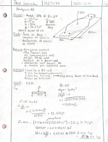
Analysis 2
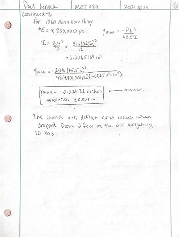
This analysis was done to determine if the chassis design could withstand a 20 foot drop without deflecting more than 0.1 inches. It was found that the chassis design is made out of aluminum with a thickness of 0.25 inches would only deflect 0.03 inches which is well within the range specified. This analysis is displayed in Figures 3 and 4.
Figure 3: Analysis 2
Figure 4: Analysis 2(continued)
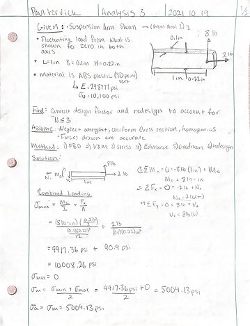

Analysis 3
This analysis was revisiting the design parameters produced in the first analysis but for a more realistic fluctuating load and increasing the design factor to 3 which makes the design much safer. It was determined that the suspension tower arm would have increased cross-sectional dimensions of 0.2 inches by 0.4 inches. This analysis is displayed in Figures 5 and 6.
Figure 5: Analysis 3
Figure 6: Analysis 3(continued)

Analysis 4
Analysis 4 was seeking to find the optimal cross-sectional area for the front bumper on the RC car to be able to withstand an impact whilst going 30 mph. It was found using kinematics and mechanics of materials that the cross-section would be 0.2 inches by 0.2 inches. This analysis is displayed in Figure 7.
Figure 7: Analysis 4


Analysis 5
Analysis 5 was revisiting the design parameters produced in analysis 4. This analysis was examining the maximum bending stress at the most critical point in the front bumper to ensure that when there is the force of impact the number won't yield. It was found that for this to work the height of the cross-section had to be increased to 0.33 inches. This can be seen in figures 8 and 9.
Figure 8: Analysis 5
Figure 9: Analysis 5 (continued)

Analysis 6
This analysis was done to determine the length of the A-arm or control arm. Using the desired length of the suspension strut and the desired angle at which the control arm would sit the law of sines could be utilized to determine the length of the control arms. It was found that the control arm would have a length of 2.88 inches. This analysis can be seen in figure 9.
Figure 9: Analysis 6
Analysis 7
This analysis was done to determine the optimal thickness of the suspension tower that would be able to withstand a horizontal load of 10 pounds with a deflection under 0.05 inches. It was found that the thickness of the body of the suspension tower needed to be 0.2 inches. This analysis can be seen in figure 10.
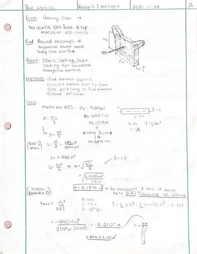
Figure 10: Analysis 7

Analysis 8
This analysis was done to determine the required screw size for the connection from the suspension tower to the chassis. This was assuming that the crew would have to be able to withstand a shear force of 10 pounds. it was found that a 1/16th inch screw would work well. This analysis can be seen in figure 11.
Figure 11: Analysis 8
Analysis 9
This analysis was done to determine the K value for the springs on the suspension sturts that would allow the suspension to withstand the force of a 3-foot drop. It was found that the K value would be 1075 lbf./ft. This analysis can be seen in figure 12.

Figure 12: Analysis 9

Analysis 10
Analysis 10 was seeking to find all the mounting locations of all of the components on the chassis. Using all the dimensions of the components each mounting location coordinate was found. This analysis can be seen in figure 13.
Figure 13: Analysis 10
Analysis 11
This analysis was seeking to find what the length of the control arm needed to be to allow for a 45-degree rotation of the front wheels. It was found that the control arms needed to be at least 2.9 inches long. This analysis can be seen in figure 14.

Figure 14: Analysis 11

Analysis 12
This analysis was seeking to find the optimal material of the pin that connects the control arm to the chassis. It also was looking to find the maximum deflection in the control arm when a 10-pound load is applied horizontally to the wheel connection point. It was found that the pin would be made out of 6061 aluminium alloy. This analysis can be seen in figures 15, 16 and 17.
Figure 15: Analysis 12

Figure 16: Control-arm max deflection
